
Rosemount 5300 Manual: A Comprehensive Overview
This manual details the Rosemount 5300 Series, a guided wave radar level and interface transmitter, offering superior performance and reliability.
It covers installation, configuration, troubleshooting, and safety certifications up to SIL3, referencing revisions DA, GA, and HC.
The Rosemount 5300 Series represents a significant advancement in level and interface measurement technology, utilizing Guided Wave Radar (GWR). This transmitter is designed for demanding applications across diverse industries, providing robust and accurate performance. Emerson’s Rosemount 5300 offers industry-leading measurement capabilities, built upon the foundation of Direct Switch Technology (DST).
Initially released in December 2010 (Rev DA), and subsequently updated with revisions GA (June 2015) and HC (March 2016), the 5300 Series has consistently evolved to meet increasingly complex process requirements. These transmitters are not merely level indicators; they are critical components in process optimization and safety systems. The series is now certified to IEC 61508 for Safety Instrumented Functions (SIF) up to SIL 3, demonstrating a commitment to operational safety and reliability. Understanding the nuances of each revision, particularly the DD_REV parameter indicating the oldest compatible device description, is crucial for seamless integration and operation.
Key Features and Benefits
The Rosemount 5300 Series boasts several key features contributing to its widespread adoption. Its core strength lies in Direct Switch Technology (DST), delivering an echo signal significantly stronger – two to five times – than previous generations. This enhanced signal strength translates to improved reliability and accuracy, even in challenging process conditions.
Furthermore, the series offers superior performance in level and interface measurement, crucial for optimizing processes and reducing operational costs. Safety is paramount, evidenced by its certification to IEC 61508 for SIL2 (and now up to SIL3) applications. The availability of multiple product data sheet revisions (DA, GA, HC) ensures compatibility and access to the latest enhancements. The DD_REV parameter facilitates smooth integration with existing systems. Ultimately, the Rosemount 5300 provides a dependable and safe solution for critical level measurement needs.
Applications of the Rosemount 5300
The Rosemount 5300 Series Guided Wave Radar transmitter excels in a diverse range of industrial applications. It’s ideally suited for level measurement in tanks and vessels containing liquids, slurries, and solids, offering reliable performance regardless of process variations.
Its interface measurement capabilities make it valuable in separating oil and water, or identifying distinct layers within a process stream. The transmitter’s robustness allows deployment in demanding environments, including those requiring safety instrumented systems (SIL) compliance. Industries benefiting from the 5300 include chemical processing, oil & gas, refining, and water/wastewater treatment. The device’s accuracy and dependability contribute to improved process control, reduced product loss, and enhanced safety across these sectors, making it a versatile solution for complex measurement challenges.
Technical Specifications
The Rosemount 5300 utilizes Guided Wave Radar (GWR) and Direct Switch Technology (DST), requiring specific power and electrical connections detailed within this manual.
Operating Principles: Guided Wave Radar (GWR)
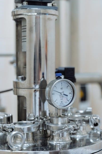
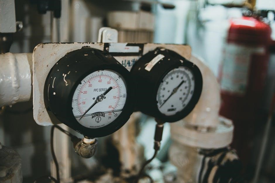
The Rosemount 5300 Series employs Guided Wave Radar (GWR) technology for precise level and interface measurement. Unlike free space radar, GWR utilizes a probe – a waveguide – to guide the radar signal. This method mitigates interference from obstructions within the vessel, such as mixers or internal structures, providing reliable readings even in challenging applications.
The transmitter emits a microwave pulse that travels down the probe and reflects off the process fluid’s surface. The time it takes for the signal to return determines the distance to the liquid level. GWR is unaffected by changes in density, temperature, pressure, or dielectric constant of the process fluid, offering consistent performance.
Furthermore, the guided wave approach minimizes the impact of foam or vapor, enhancing accuracy and reliability. This technology is particularly well-suited for applications involving difficult or varying process conditions, delivering robust and dependable level measurement.
Direct Switch Technology (DST) Explained
Direct Switch Technology (DST) is a core innovation within the Rosemount 5300 Series, significantly enhancing signal strength and reliability. Traditional time domain reflectometry (TDR) can suffer from signal loss, particularly in challenging applications with varying process conditions. DST overcomes this limitation by directly switching the signal between transmit and receive modes.
This switching process generates an echo signal that is demonstrably stronger – two to five times more powerful – than previous generation technologies. The amplified signal improves the transmitter’s ability to detect weak reflections, especially in applications involving low dielectric materials, foam, or vapor.
Consequently, DST provides more accurate and dependable level measurements, reducing the likelihood of false readings and improving overall process control. This technology contributes to the Rosemount 5300’s reputation for industry-leading performance and reliability.
Power Requirements and Electrical Connections
The Rosemount 5300 Series transmitters operate with a wide range of power supplies, accommodating diverse installation environments. Typically, they require 18 to 35 VDC, ensuring compatibility with standard process control systems. Careful attention to polarity is crucial during electrical connections to prevent damage.
Wiring configurations support both two-wire and four-wire connections, offering flexibility in system design. Proper grounding is essential for optimal performance and safety, minimizing noise and ensuring accurate measurements. Connection types include standard threaded connections, facilitating easy integration.
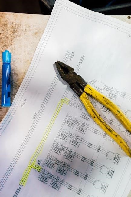
Detailed wiring diagrams are provided in the product documentation, outlining specific connections for power, signal output (typically 4-20mA HART), and communication protocols. Adherence to these guidelines is vital for reliable operation and maintaining the transmitter’s certifications.
Installation and Configuration
Proper mounting, wiring, and initial setup are critical for optimal Rosemount 5300 performance. Detailed instructions ensure accurate level and interface measurements, maximizing reliability and safety.
Mounting and Mechanical Installation
Careful mechanical installation is paramount for the Rosemount 5300’s accuracy and longevity. The transmitter can be mounted in various configurations, including single or dual probe setups, depending on the application requirements.
Ensure the mounting surface is stable and capable of supporting the transmitter’s weight. Proper alignment of the probe is crucial; it must be vertically aligned with the process connection to prevent measurement errors.
Consider the process conditions, such as temperature and pressure, when selecting mounting hardware. Utilize appropriate sealing materials to maintain a leak-tight connection. Avoid mounting the transmitter in areas prone to vibration or mechanical shock, as this can affect performance.
Refer to the detailed mechanical drawings in the product data sheet (Rev. DA, GA, or HC) for specific dimensions and mounting recommendations. Always follow established safety procedures during installation.
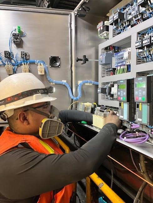
Wiring and Electrical Installation
Proper electrical installation is critical for safe and reliable operation of the Rosemount 5300. Before commencing any wiring, ensure the power supply is disconnected and lockout/tagout procedures are followed.
The transmitter supports various power supply options; consult the product data sheet (Rev. DA, GA, or HC) for specific voltage and current requirements. Utilize appropriately sized wiring and ensure secure connections to prevent voltage drops or signal interference;

Grounding is essential for safety and electromagnetic compatibility (EMC). Connect the transmitter’s grounding terminal to a reliable earth ground.
Carefully observe polarity when connecting the power supply. Incorrect wiring can damage the transmitter. Refer to the wiring diagrams provided in the documentation for correct terminal assignments. Shielded cable is recommended in environments with high electrical noise. Verify all connections before applying power.
Initial Configuration and Setup
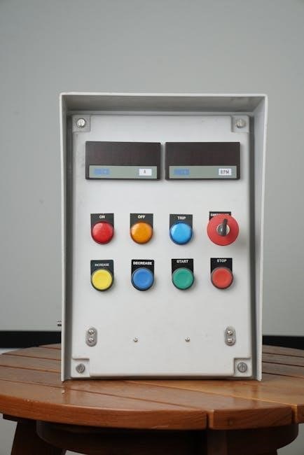
After electrical installation, initial configuration of the Rosemount 5300 is essential. Power up the transmitter and allow it to stabilize. Access the transmitter’s configuration interface using a HART communicator or Emerson’s AMS software.
Begin by setting the basic parameters, including the measurement units (e.g., feet, meters), the application type (level or interface), and the probe type. Configure the zero and span values to match the vessel’s dimensions and the expected operating range.
Pay close attention to the DD_REV parameter, which indicates the oldest revision of the device description file. Ensure compatibility with your configuration software.
Perform a guided setup wizard to simplify the process. Verify the readings and adjust parameters as needed to optimize performance. Document all configuration settings for future reference.
Advanced Configuration & Troubleshooting
Detailed parameter configuration (DD_REV) and troubleshooting guides are crucial. This section covers resolving common issues and understanding SIL3 certification for safety.
Parameter Configuration Details (DD_REV)
The DD_REV parameter within the Rosemount 5300 configuration is fundamentally important for device compatibility and functionality. It specifically indicates the oldest revision number of the Device Description (DD) file that accurately describes the transmitter’s capabilities. This numerical value is crucial when integrating the 5300 with various control systems and host applications.
Understanding DD_REV ensures seamless communication and proper interpretation of device data. A lower DD_REV value signifies compatibility with older system software, while a higher value indicates support for newer features and functionalities.
Careful consideration of this parameter is vital during system upgrades or when replacing transmitters. Utilizing an incompatible DD can lead to communication errors or inaccurate readings. The documentation highlights that DD_REV represents the numerically smallest revision, ensuring backward compatibility. Regularly checking and updating the DD files associated with the Rosemount 5300 is recommended for optimal performance and to leverage the latest advancements.
Troubleshooting Common Issues
Effective troubleshooting of the Rosemount 5300 relies on a systematic approach to identify and resolve potential problems. Common issues often relate to signal strength, inaccurate level readings, or communication failures. Initial checks should verify proper power supply and wiring connections, ensuring adherence to specified requirements.
If readings are unstable, investigate potential obstructions or buildup on the probe, as this can interfere with the guided wave radar signal. Confirm correct parameter configuration, particularly regarding material properties and vessel geometry. Communication errors may stem from incorrect network settings or incompatible DD files – referencing the DD_REV parameter is crucial.
For persistent issues, consult the detailed diagnostics available through the transmitter’s interface or HART communication. Regularly reviewing the manual and Emerson’s support resources can expedite resolution. Remember to document all troubleshooting steps and findings for future reference and potential escalation.
Safety Instrumented Systems (SIL) Certification (up to SIL3)
The Rosemount 5300 Series is certified to IEC 61508 for Safety Instrumented Systems (SIS), reaching a Safety Integrity Level (SIL) of 3. This certification validates its suitability for critical safety applications where reliable level and interface measurement is paramount. Achieving SIL compliance requires careful consideration during all phases – from design and installation to operation and maintenance.
Proper configuration, including redundant wiring and diagnostic coverage, is essential to meet SIL requirements. The transmitter’s Direct Switch Technology (DST) contributes to enhanced diagnostic capabilities, enabling faster detection of potential failures. Thorough documentation of the safety lifecycle, including hazard analysis and proof testing, is mandatory.
Users must adhere to Emerson’s guidelines and industry best practices to maintain SIL integrity. Regular audits and verification of safety functions are crucial for continued compliance and operational safety.
Documentation and Resources
Access product data sheets (Rev. DA, GA, HC) and software downloads for the Rosemount 5300 Series. Comprehensive documentation supports installation and configuration needs.
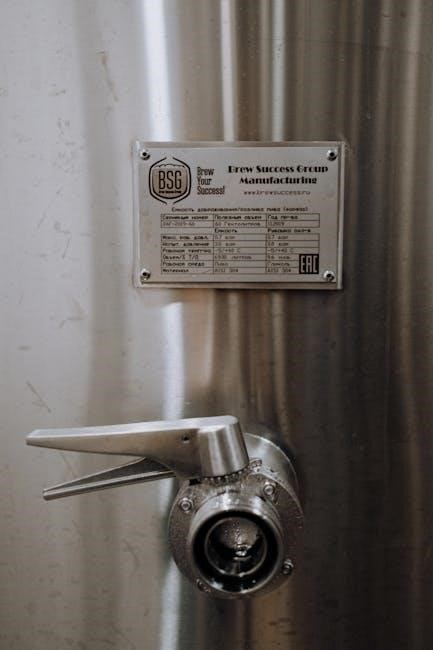
Product Data Sheet Versions (Rev. DA, GA, HC)
Multiple revisions of the Rosemount 5300 Series Product Data Sheet are available, each reflecting updates and refinements to the transmitter. The earliest documented version, Rev. DA (December 2010, document number 00813-0100-4530), highlights the superior performance of the guided wave radar level and interface transmitter, emphasizing industry-leading measurement capabilities enabled by Direct Switch Technology (DST).
Rev. GA (June 2015, document number 00813-0100-4530) continues to showcase these features, noting safety certification to IEC 61508 for SIL2 applications. Further enhancements are detailed in Rev. HC (March 2016, document number 00813-0100-4530), maintaining the focus on reliable level and interface measurement. These data sheets provide critical specifications, application guidance, and installation details for users, ensuring optimal performance and safety when deploying the Rosemount 5300.
Software and Downloads
Access to essential software and documentation for the Rosemount 5300 Series is readily available through the Yokogawa Electric Corporation website. Users can download the Rosemount 5300 Series (Guided Wave Radar Level and Interface Transmitter) Rev.4-5 software package (411.8 KB), facilitating configuration, diagnostics, and maintenance of the device.
This software supports parameter configuration, including access to the DD_REV parameter, which indicates the oldest revision number of the Device Description (DD) file. Proper software versions are crucial for seamless integration and optimal performance. Regularly checking for updates ensures compatibility and access to the latest features and bug fixes. The downloads section provides a centralized location for all necessary resources, streamlining the user experience and maximizing the benefits of the Rosemount 5300 system.